
So, this is definitely one of my favourite projects thus far. It obviously required some money and due to the electronic component shortage, finesse.
Obviously the first place to start was with google, I found some good instructables which proved the concept.
https://www.instructables.com/Programming-PIC-Microcontrollers/
https://www.instructables.com/Introduction-98/
The main parts here proved for me:
- Its possible as a hobbyist
- You can use a breadboard rather than having a PCB manufactured
So my first place to start was picking a microchip of course and looking on RS Components I quickly decided upon Microchips’ PIC32 family. The main reason was the complete package, the IDE + all the excellent documentation such as “Getting Started” with the “Minimal Requirements setup” overview, telling me exactly what I needed.
When I first selected a PIC, I went for the PIC32MX520 however when pay day rolled around and I began looking at the necessary capacitors I found most to be, well, months away. So I revisited my choices and opted for a PIC32MX250 as I could get the parts relatively quickly and without having to buy in huge quantities of 100’s. Here is the parts list I ended up with:
- Tantalum Capacitors – Solid Leaded 20volts 0.1uF 10%
- TE Connectivity 330Ω Carbon Film Resistor 0.33W ±5% CFR25J330R
- KEMET 10μF MnO2 Tantalum Capacitor 16V dc, T350 Series
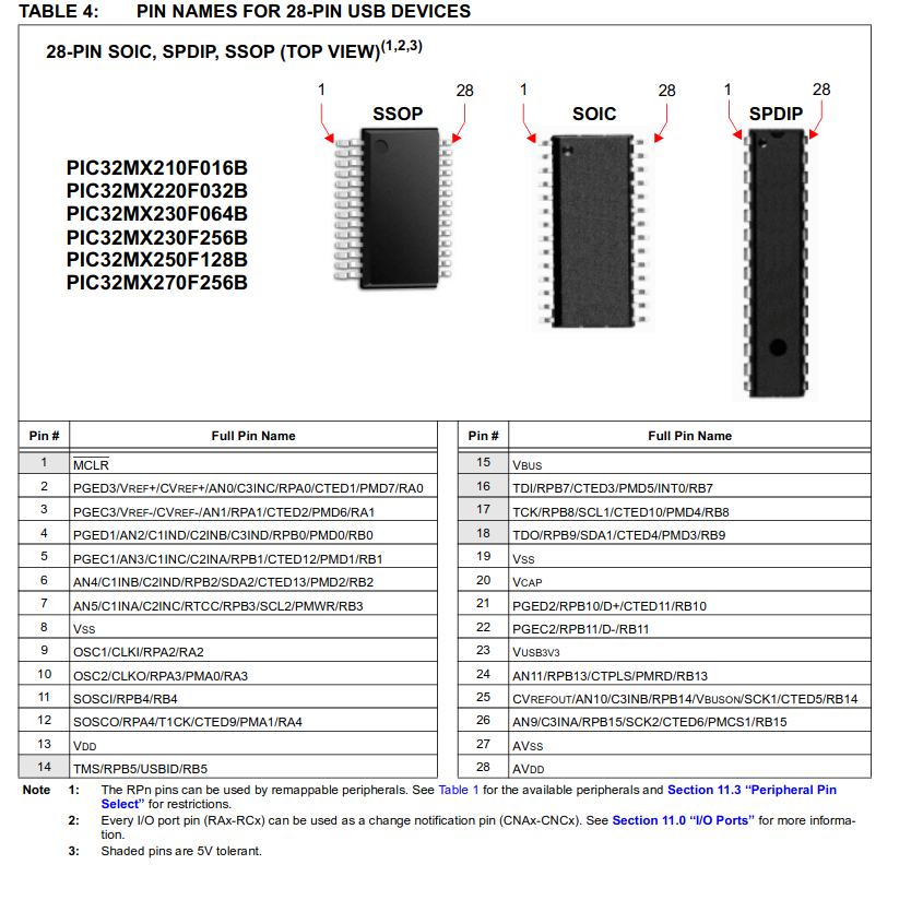
- Microchip PIC32MX250F128B-I/SP, 32bit PIC Microcontroller, PIC32MX, 40MHz, 128 kB Flash, 28-Pin SPDIP
Now some other items were supplemented by my pre-existing start kit and raspberry kit. Such as the breadboard, cables for it, LED, power supply from the pi, 10kOhm and 1kOhm resistors. Quantities wise it turns out I over-orded, we’ll get to that later…
In ordering, the first mistake however was a misinterpretation of the manual and I thought I needed a PICkit 2. This was an unfortunate mistake.
I tried working around it and found several programs online for linux which claimed capability (pic32prog). I then had troubles compiling, if you do try and get this working, https://github.com/sergev/pic32prog one tip is to jump into the hidapi directory and run “./bootstrap”, this reconfigures the automake tools for your environment, that wasted an hour trying to figure that out. You may also need to define the host in your ./configure with “./configure host=linux”.
Brushing past that, when I finally looked into the manuals for the PICkit 2, surprise surprise, no PIC32 family listed under supported hardware. But when I go to the PICkit 3 manual, it is. So, forked out a bit more cash and bought that.
My next mistake and WARNING: if it doesn’t work, try a different power supply. I had bought an independent power supply which can do a range of voltages including 3.3V but it never seemed to work, in the IDE it would argue that VDD was not detected, clearly stating that my power was not present. Ultimately I used my raspberry pi’s 3.3V output on the expansion board as my power supply.
I still had some issues though, so how to fix this? Well, let’s first cover the IDE before jumping into that. Well, I recommend and of course, is recommended by Microchip, MPLABX IDE, in order to install on a 64 bit version you may need to run the steps identified here: https://unix.stackexchange.com/questions/162575/where-can-i-find-the-32-bit-libraries-needed-to-run-mplab-x. The installation on linux is fairly straight forwarded, starting it however, not so much! You need to open terminal and run:
mplab_ideOnce it opens up, select New Project and select the PIC32MX template:
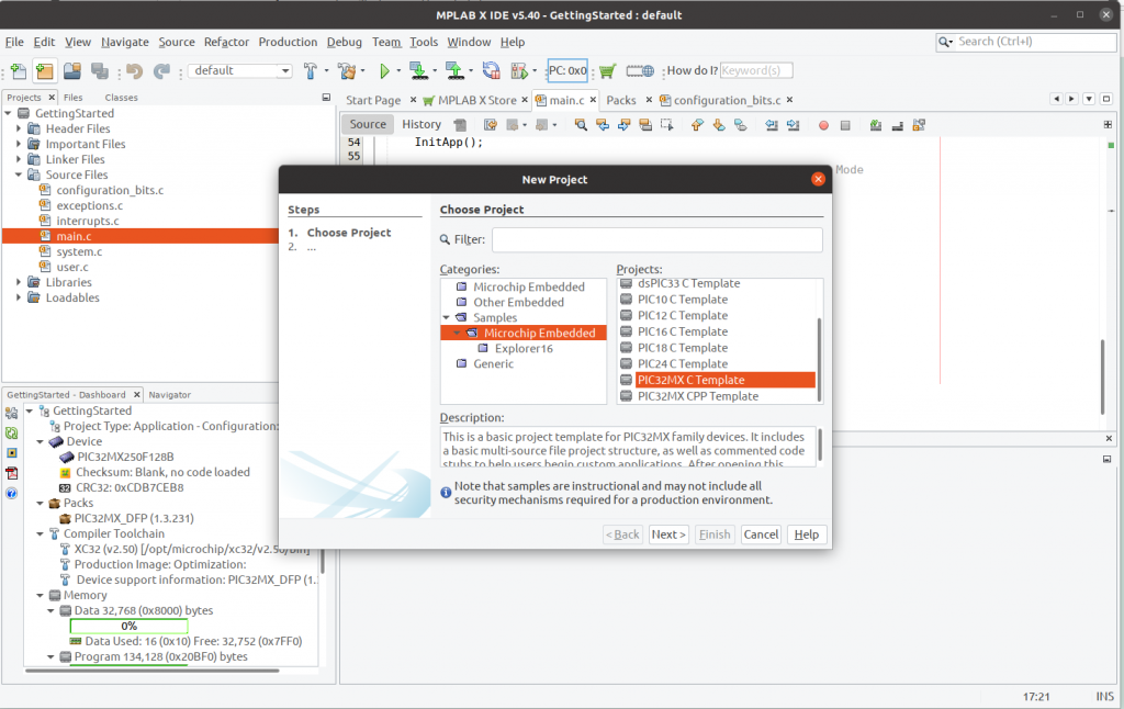
Now, this won’t default to your magical microchip so we need to configure this. You may also get this error:
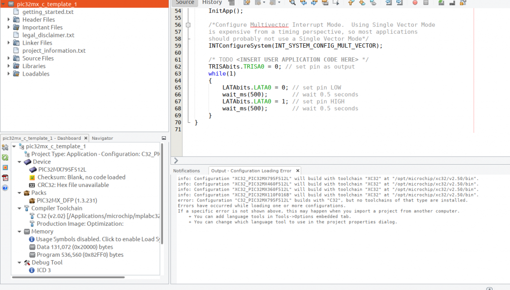
In the output, don’t worry, we need to select a different compiler, the XC32 compiler, this was renamed a while back and version numbering reset but seems they didn’t update the templates.
Click the little spanner:
Click, Manage Configurations:
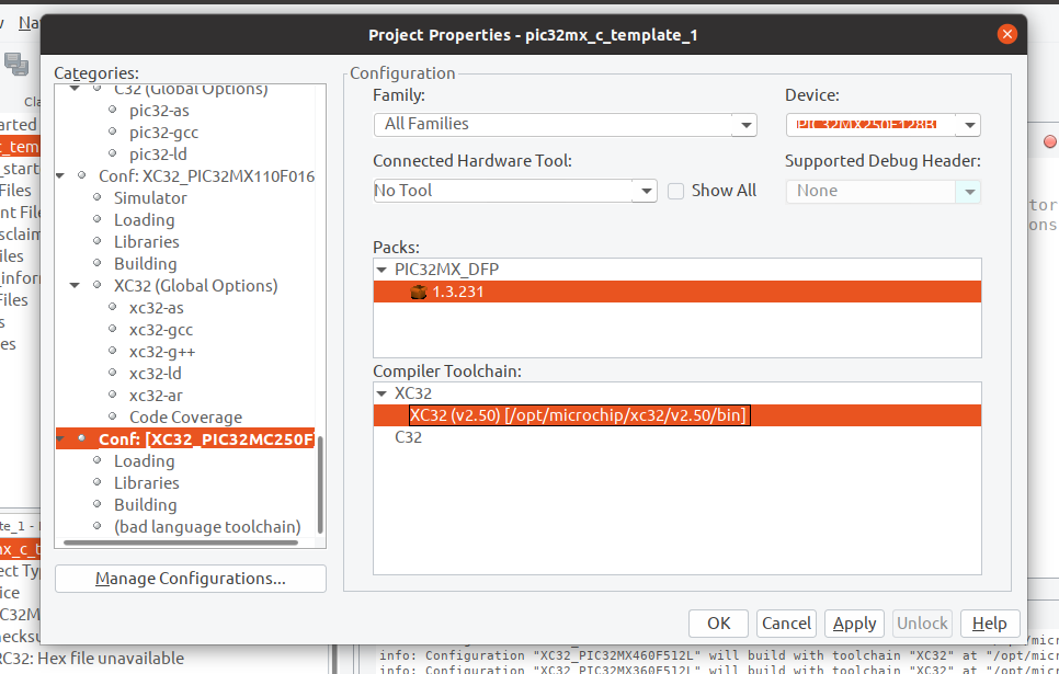
Select to create a new one and name it after your chip with XC32 to note the compiler we want.
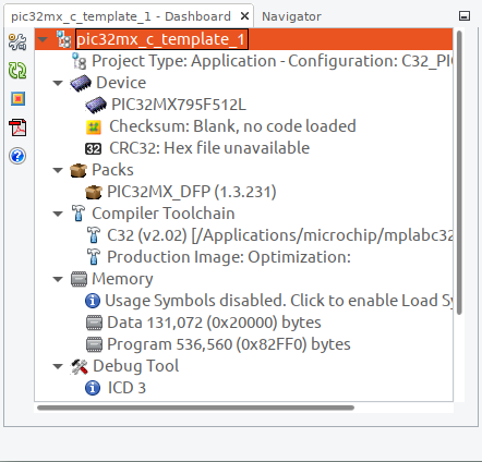
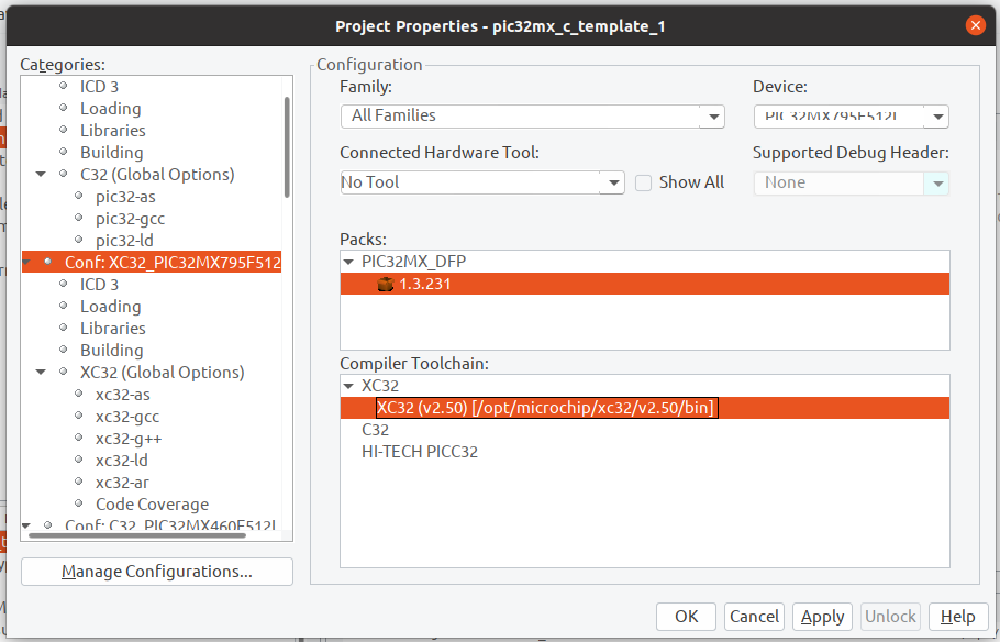
Set as Active and click OK. The new configuration will be at the bottom of the list, go to it and then select your device and toolchain as XC32:
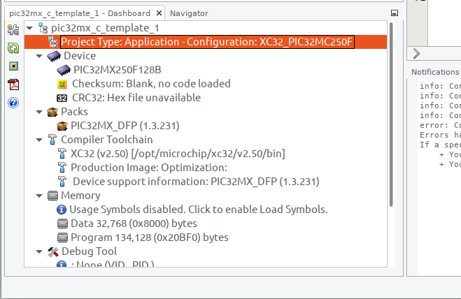
Click OK, we should be done there. Now your project should have the correct device selected with the template of all the source files we need:
Now, let’s get back to the instructables I mentioned earlier and follow it now that we’re setup correctly:
https://www.instructables.com/Programming-PIC-Microcontrollers/
A part where it deviates from newer version of the IDE is where to find configuration bits. I can’t seem to screenshot it in Linux, so I’ll have to just mention it’s under Windows->Target Memory Views-> Configuration Bits. To be honest though, I didn’t see any reason to do anything here so kept it all at it’s defaults and moved on, do however select “Generate Source File”, go ahead and copy and paste that into your configuration_bits.c under Source Files (don’t overwrite the template, append this to the end).
Okay, now our clock, this is pretty important because you want to know what your frequency of execution is.
Now I skipped step 6 for now as I’m not running any IO – this is referring to the oscillator driving our IO ports – not the PIC32 clock frequency. For the clock frequency I simply followed step 7 and then step 8 to create my blinking LED. Since I’m only driving an LED, I wasn’t worried about the ADC/DAC’s running faster at their 80MHz. Okay, so now to compile, but you get an error right? You’re probably missing the peripheral libraries:
https://www.microchip.com/SWLibraryWeb/product.aspx?product=PIC32%20Peripheral%20Library
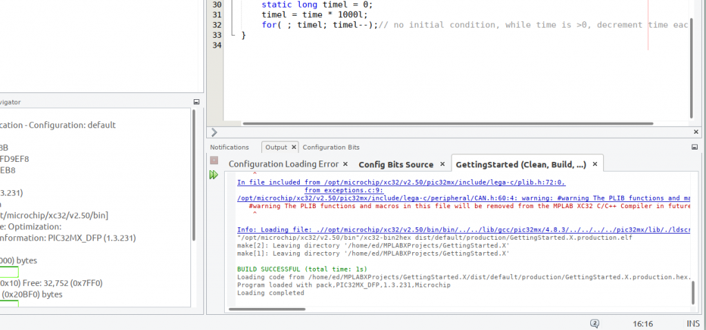
Once you have all this together, you should be able to compile (google if not, the microchip forums could also be useful to use). You’ll probably get a bunch of warnings but don’t worry if you do get the build successful:
Okay so I’ve got my HEX file, I’ve got my PICKit3, I’ve got my parts. I tried building several setups but nothing worked. The first thing that might confuse you when you look at the block diagrams, when you go to your chip on Microchip.com, select Documents and then the family datasheet, this is the most informative document I have ever found.
It’s also easy to navigate as a rareity, they actually put the PDF chapter sections in! So let’s go to Chapter 2, “GUIDELINES FOR GETTING STARTED WITH 32-BIT MCUs”.
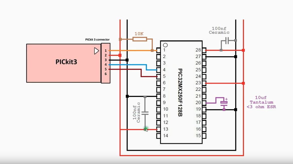
Read through, scroll down and you’ll find the diagram:
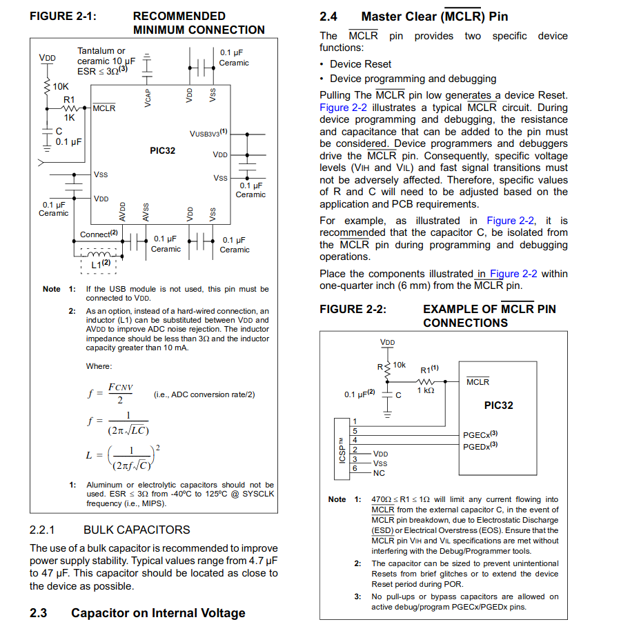
Note: It’s pretty particular with what capacitor to use, because most of these are found in surface mount form I had to expand the restrictions to find something that worked and ignore the advice around which material to use… bit dangerous for power regulation I know.
Second note: You’ll see that for every Vss, there’s a Vdd, so easy to connect our capacitor across right? Depends on the microchip. As you can see, mine had a surplus of Vss:
Now, I assumed I just connect both up to the one Vdd. Nothing however worked, kept getting errors, a mixture of my setup and the power supply. I knew I didn’t get the Vdd error not detected when I used my pi as the power source so set that up. Then, the next error, vain of an engineers life! But once you have a working setup, you have a setup. So, thank you to this chap:
https://www.youtube.com/watch?v=-wRhw8HMNnc&t=247s
For some reason embedding’s not working for this youtube video, maybe he’s disabled that option. The overview he gave was this:

It’s not explicit in the manual that VCap can be used for the purpose of regulating Vss, it just says connect to ground so I like this chaps solution.
Anyway, this then was detected and when I selected make and deploy (the chip image with a down arrow):

I got a programming/verify successful message, yay! Now I restarted the microchip simply by disconnecting and reconnecting the power supply. Note: My configuration also had a connection from pin 2 to a 330Ohm resistor, then to a green LED, finally to ground as we’re running the code from Step 8 and need some way to verify that we have actually programmed the chip and got it up and running. Finally, I end up with this:
What next? Well, getting an analog input, that’s easy. The complex part will be to somehow connect it to a WiFi network and send a POST action to my server so I can see the value of the analog input. Stay tuned!